dream it
〰️
dream it 〰️
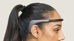
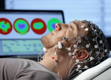
Research-grade EEG electrodes are hard to install, uncomfortable, and not particularly reusable. There are some new commercial headsets such as the Muse, Neurosity, or the Emotiv among others that use dry electrode systems, but they are expensive and can’t really be customized to each user.
For this project, my goals were 1. To understand the general electronics system behind EEG recording by building my own, 2. Integrate these cool custom 2-p 3D printed dry microelectrode arrays I designed with my collaborators at MIT Media Lab, and 3. Design a sleek, jewelry-inspired headset or earring to allow for independent, wireless use. In addition to wireless EEG measurements, this device platform will take inertial measurement unit (IMU) and audio recordings with the XIAO nrf52840 Sense microcontroller.


design
🏗️
design 🏗️
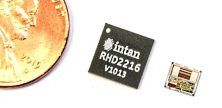
While I would love to slowly learn the specific electronics needed to construct an electrophysiology recording system from individual discrete components, I quickly realized that this would be an uphill battle, not just due to my novice electronics knowledge, but also due to the noise and interference that would degrade the signal. It would also end up to be a much bulkier device than I designed for. My collaborators at MIT had spare Intan electrophysiology chips that implement the the filters, amplifiers, and digitization in a silicon integrated circuit chip. They are a hefty $250 and are the main/only chip on the US market, so this is clearly where a lot of the expense comes from. The chip takes 16 channels and provides a serial peripheral interface (SPI) protocol to communicate with the microcontroller. This means that I can read from 16 channels from 4-wires. Now that I had found the main components of the system, I realized that it would be a fairly simple system to design a flexible PCB to incorporate.
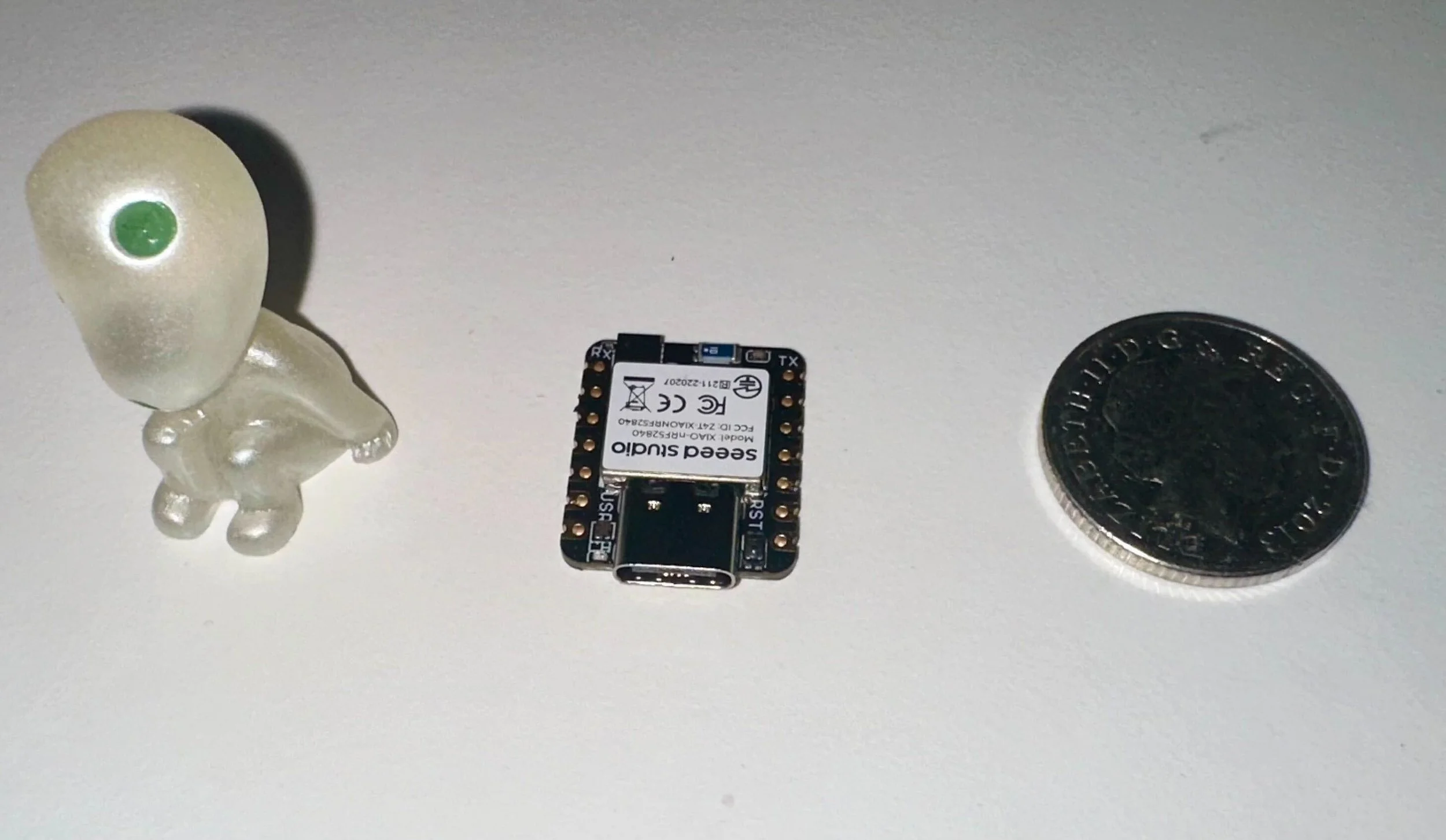
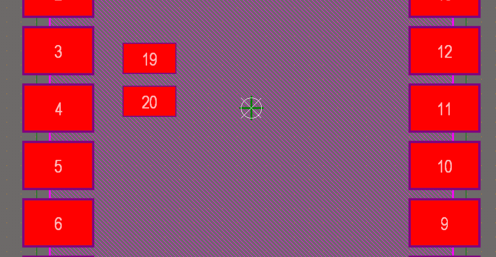
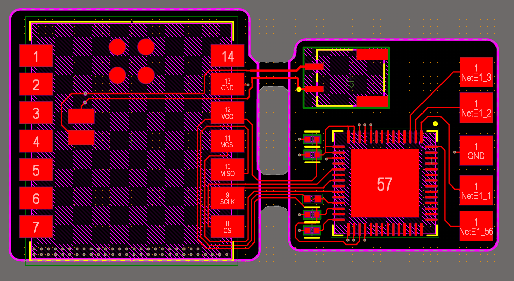
I started my PCB design in Altium to connect the microcontroller to the Intan chip using this paper as a reference. The SPI interface needs MOSI, MISO, SCK, and CSN, which are signals controlled by the microcontroller. Other than that, the chip needs some pads to connect the electrodes, and 3.3V & Ground. The XIAO microcontroller implements Bluetooth capability and also has a microphone and a accelerometer/gyroscope. These sensors are implemented in a small area on the microcontroller board itself, which can be surface soldered on the PCB I design.
In this process, I learned how to draw footprints using the datasheet as a dimensions reference. I also learned how to draw a schematic connecting the two components. Per the RHD2216 datasheet, we need to add a couple extra items such as a few 100 nF capacitors to filter out high frequency noise. With only 5 components, this is a lightweight design with a tiny area. Next, was to put the pieces together in ‘laying out’ a PCB.

build
👷🏻♀️
build 👷🏻♀️


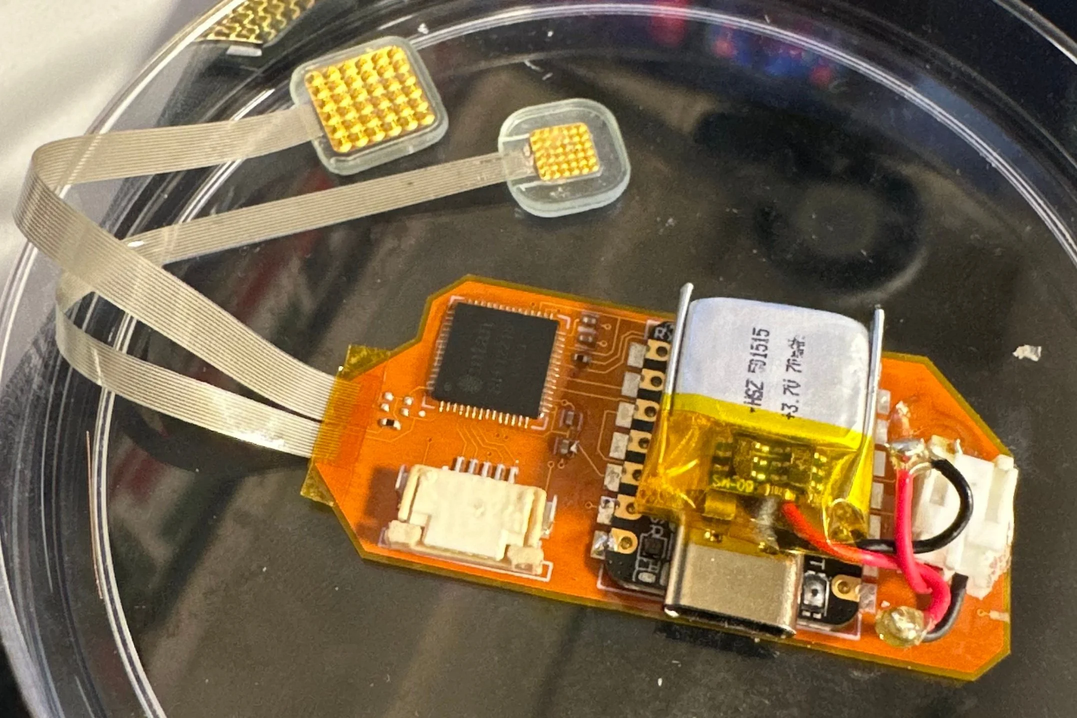
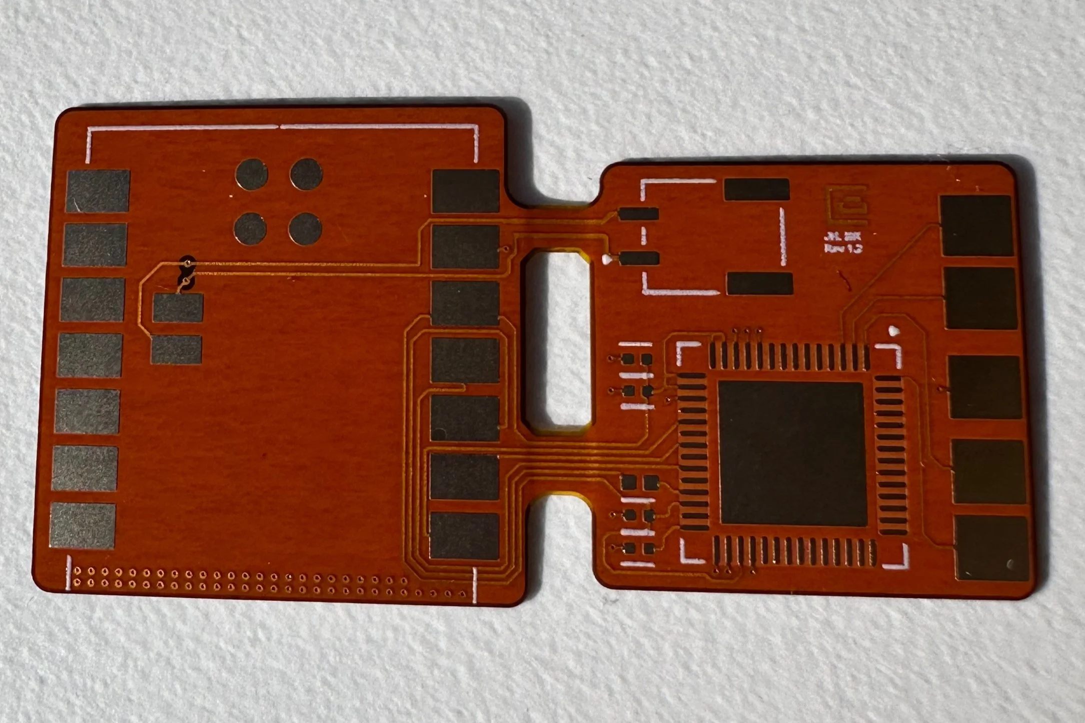
Version 1 consisted of the XIAO Sense microcontroller and the Intan RHD2215, a battery connector, and a couple pads to bond the electrodes. I used 6 mil traces on a 2 layer flexible PCB. I also defined the board outline and made sure that the components were placed close to the Ephys chip. After a design review, we sent them off to the PCB manufacturers in China!
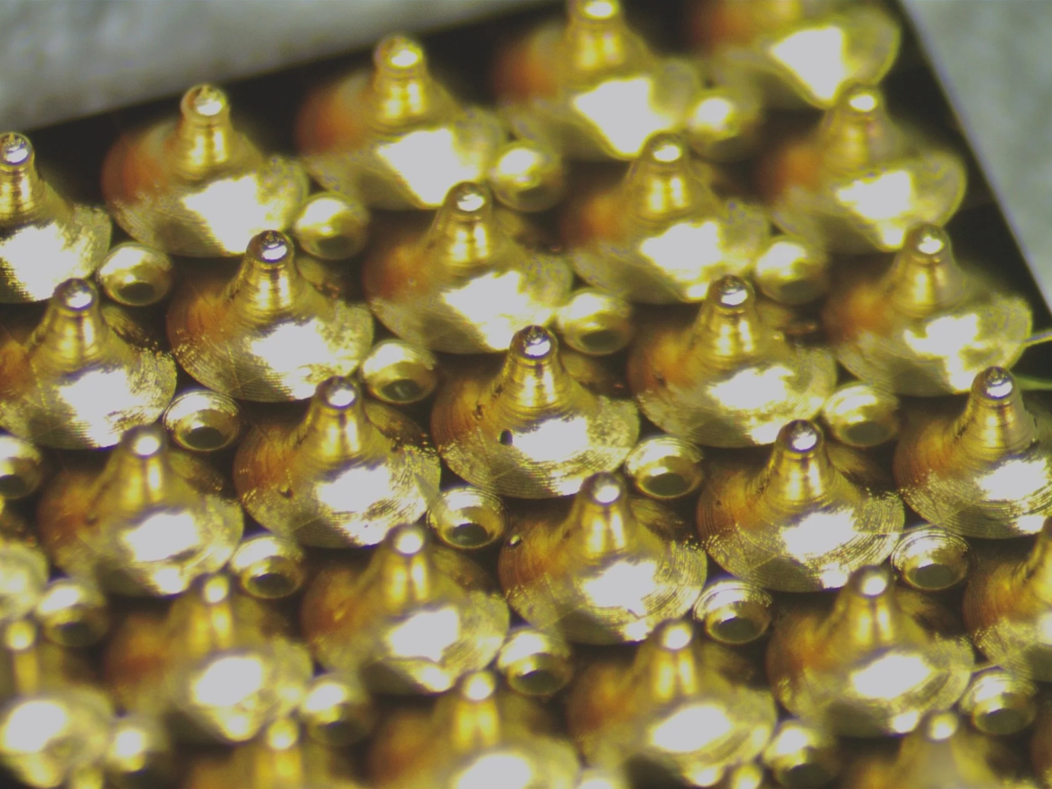
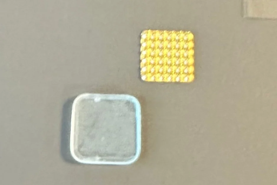
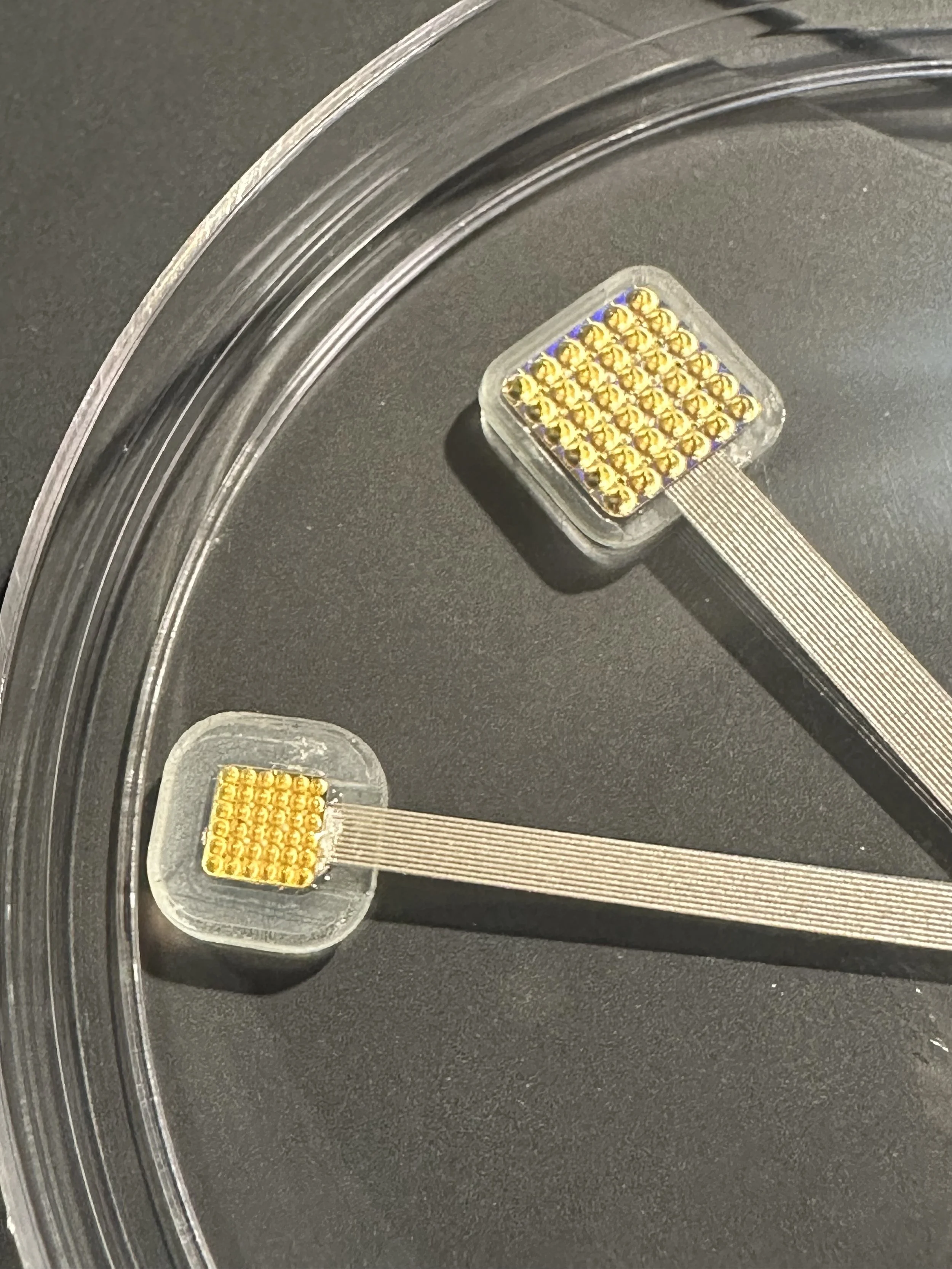
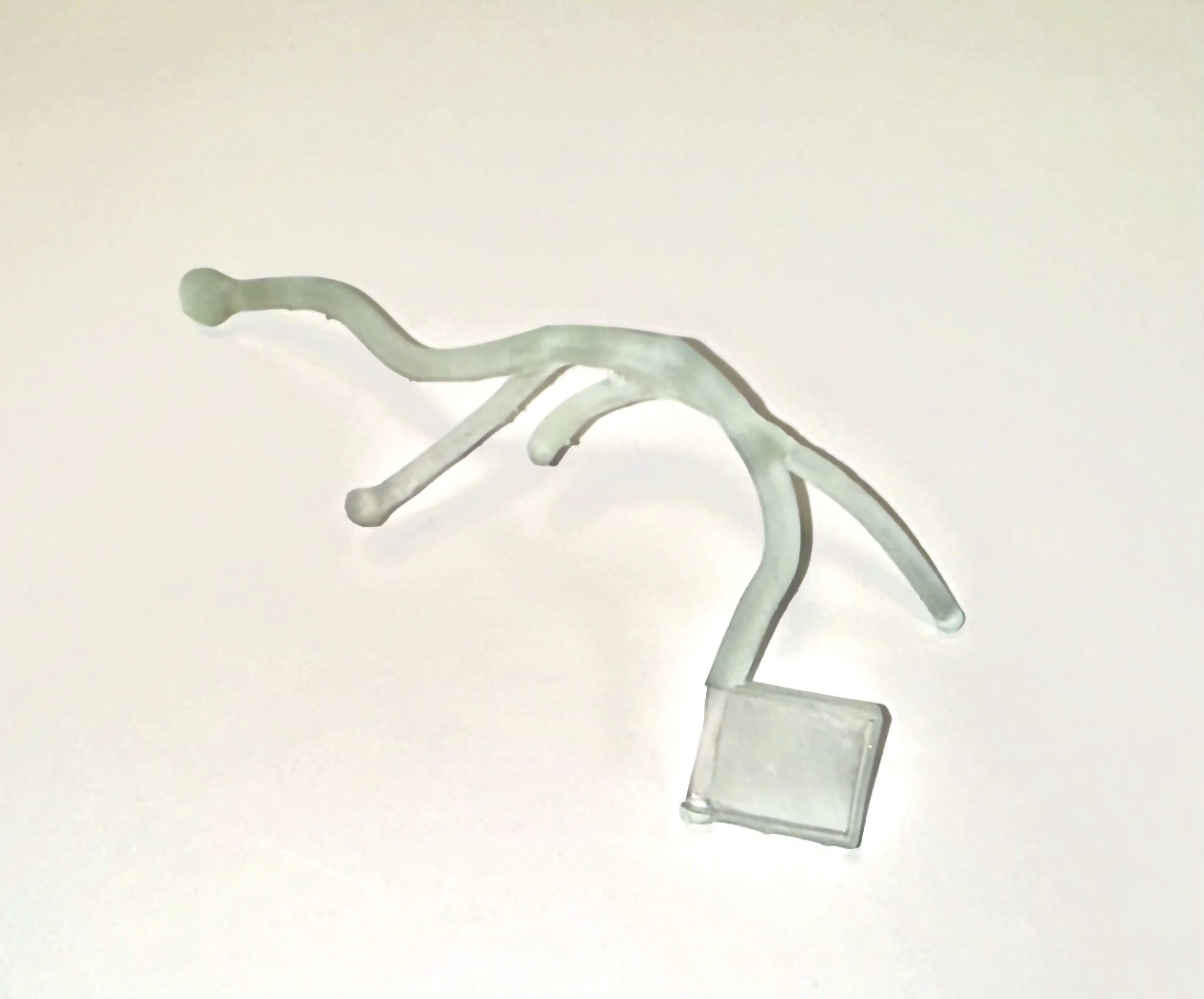
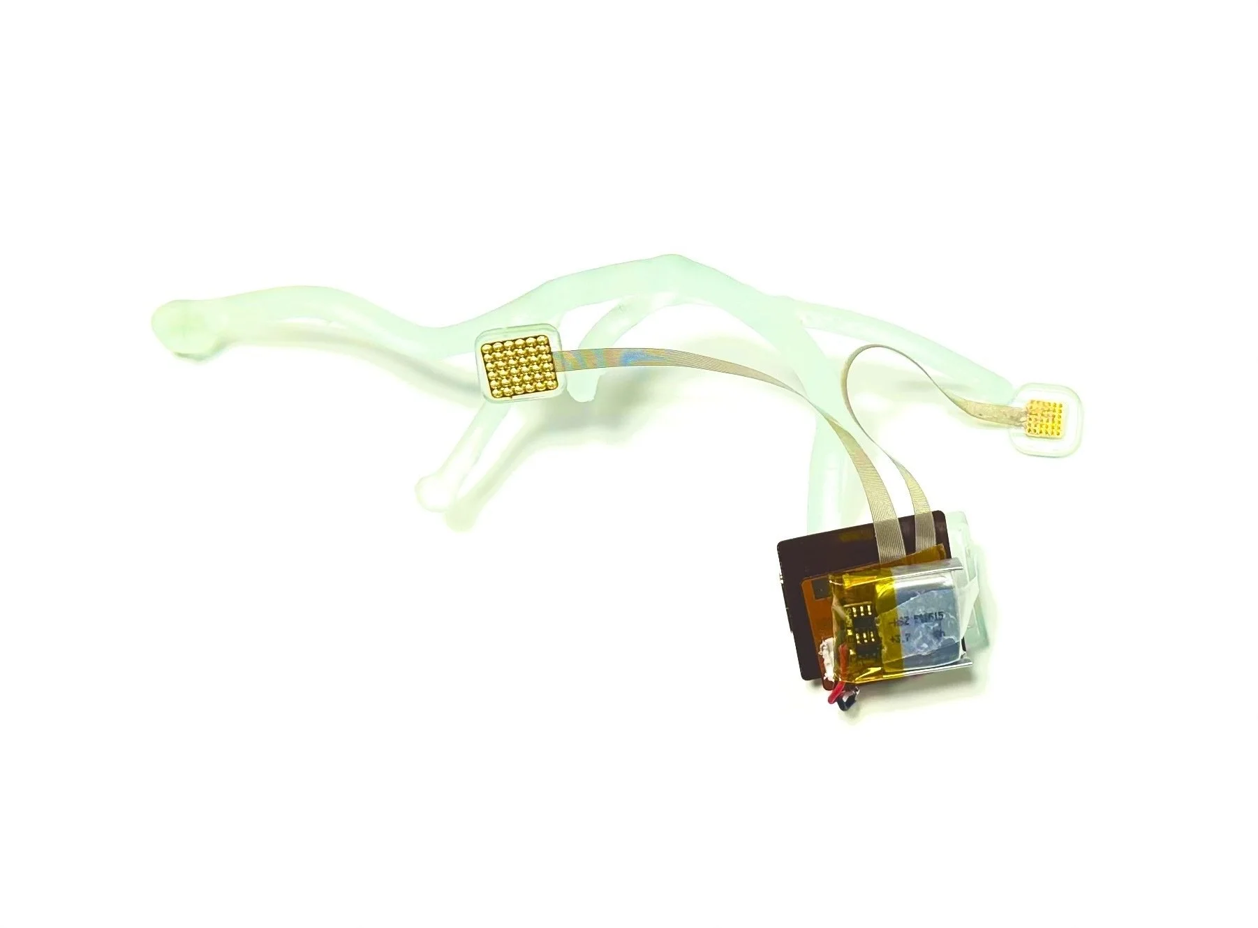
The microneedle electrode array was 3D-printed at the micro-scale using 2-photon polymerization similar to the effect used for Calcium imaging. It’s printed in a acrylic-like resin and takes isopropanol to dissolve uncured resin. To make it conductive, my collaborators coated it in a Chromium/Gold film that was less than 200 nanometers thick using RF sputtering at MIT Nano.
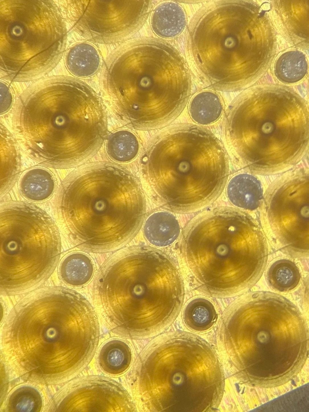
I designed the profile of the array in order to be tall enough to get around hair, but still have a sharp point in order to pierce the skin slightly. I also included some holes so that the gold could make contact to our wiring, which we would glue together with conductive epoxy (see the conductive epoxy pushing through the holes in red). The arrays were assembled on top of ACF tape, which is a plastic film with silver ink traces that are conductive on one side. With some conductive epoxy, we glued the arrays into a 3D printed housing, sandwiching the ACF tape.
After a couple of weeks, we go the boards back and were able to assemble the first prototypes! We used our stencil to apply solder paste, carefully place the components with tweezers, and then heat the PCB on a hot plate at 250C until the low-temperature solder melted and stuck to our chips. To strengthen the connection of the solder bonds, I added epoxy encapsulation. I noticed several mistakes with the board, however. The battery connections were reversed corresponding to the connector, so it could not power the board. The polyimide insulation layer was thinner than I thought, which made the PCB exert a lot of stress on the connections, which would eventually be the downfall of version 1.
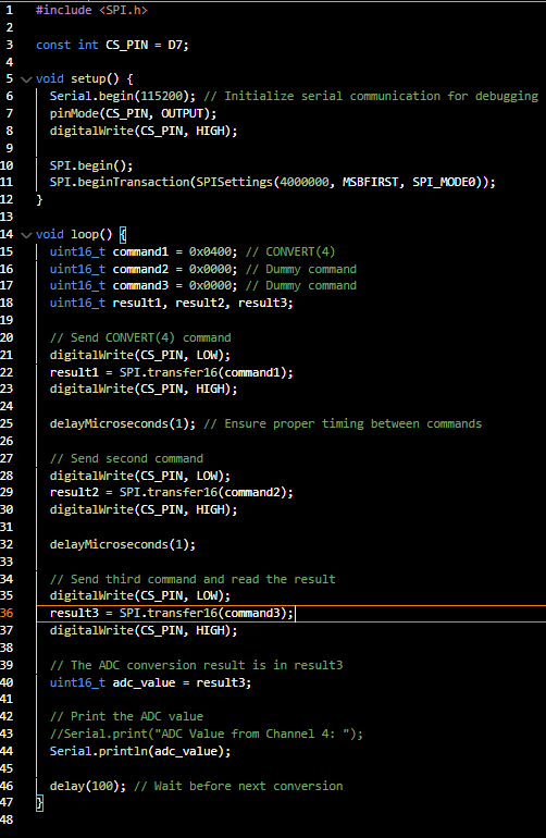
In order to get the PCB up and running, I had to write some code to get the microcontroller to talk to the Intan chip. The XIAO/nrf52840 is able to be programmed through Arduino. With some help from ChatGPT, I was able to analyze the datasheet for the RHD2216 and write a SPI driver to get data from the chip. One way to check that everything is hooked up correctly is to read from registers 40-44. If it spells, ‘INTAN’, everything is good. Otherwise, you can read the values from the electrodes of your choosing (with a delay). Unfortunately after a day of working the code started spitting out the dreaded: “It’s only returning 1’s now…”
testing v1
🧪
testing v1 🧪


Even though I was unable to connect to the chip, the microcontroller was still working and was reading fake data from the chip. It would take another couple of weeks to design and send out a new PCB, so I decided to dive deeper into the Arduino programming in order to be able to stream the ephys data over Bluetooth and take measurements from the other sensors. Using the Bleuart example, I was able to make a simple app to pair a device like a phone and start streaming through the Bleuart port in the Bluefruit app.
The bluetooth app works! I was so excited to see data streaming to my phone, even if it was through their designated app. It was again fairly easy to combine the code I previously wrote to perform SPI reads from the chip and the example code to send data to the dedicated blueart port.
building v2
🧪
building v2 🧪


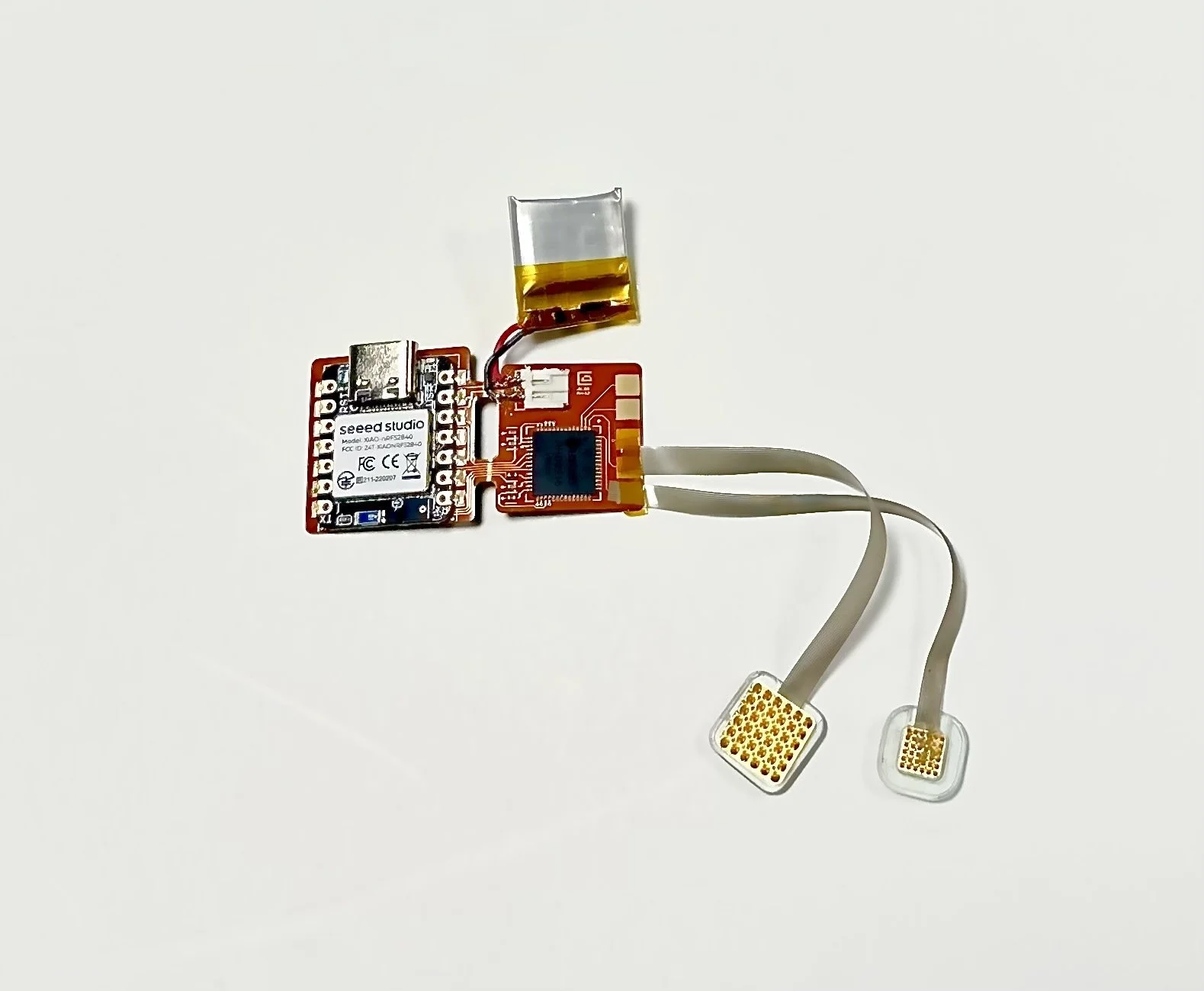
I fixed some key problems with the EEG circuit and PCB design. Some of the things I changed included: switching the battery connections, adding vias around the bluetooth antenna to help with interference, making some of the bond pads larger, and making the PCB bendable so that the device could be more compact.
I also used Nomad on the iPad to design a head-worn frame to hold the electrodes in the proper positions. While this is still a work in progress to get the fit dialed in, I was able to export the drawn scaffold to Fusion 360, make a slot to hold the device, and print it on an SLA resin printer.
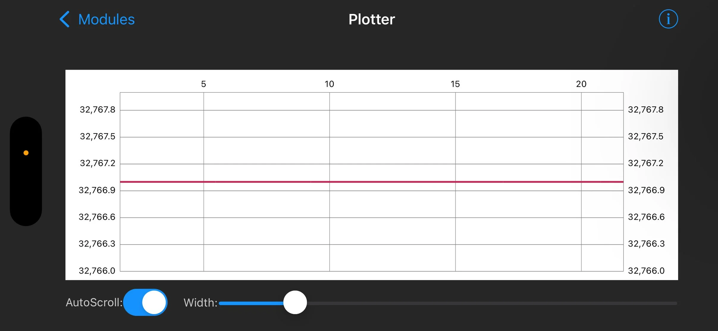
To the left are some of the first working recordings from the EEG device! You can definitely see some motion artifacts from breathing, but the signals are quite stable and are physiological! Next is to make a small application so that I can perform filtering and dissect the actual biopotential changes in the EEG bands which are in the 10-100 Hz range. More to come!